Why I build it?
Since 2021 I belong to DIPOL scientific circle. We deal with all techniques of electronic communication, and an important part of the meetings are discussions on topics related to amateur radio. Sometimes we bring a transceiver to the University of Technology, hang the antenna and make QSOs. Every member brings some parts of our temporary radioshack, like antenna tuner, antenna wire and of course radio. Due to its heavy weight, no one wants to bring a power supply. It’s a few kilograms heavy, you have to move it both ways and as a reward, you get back pain for 2 days.
Solution
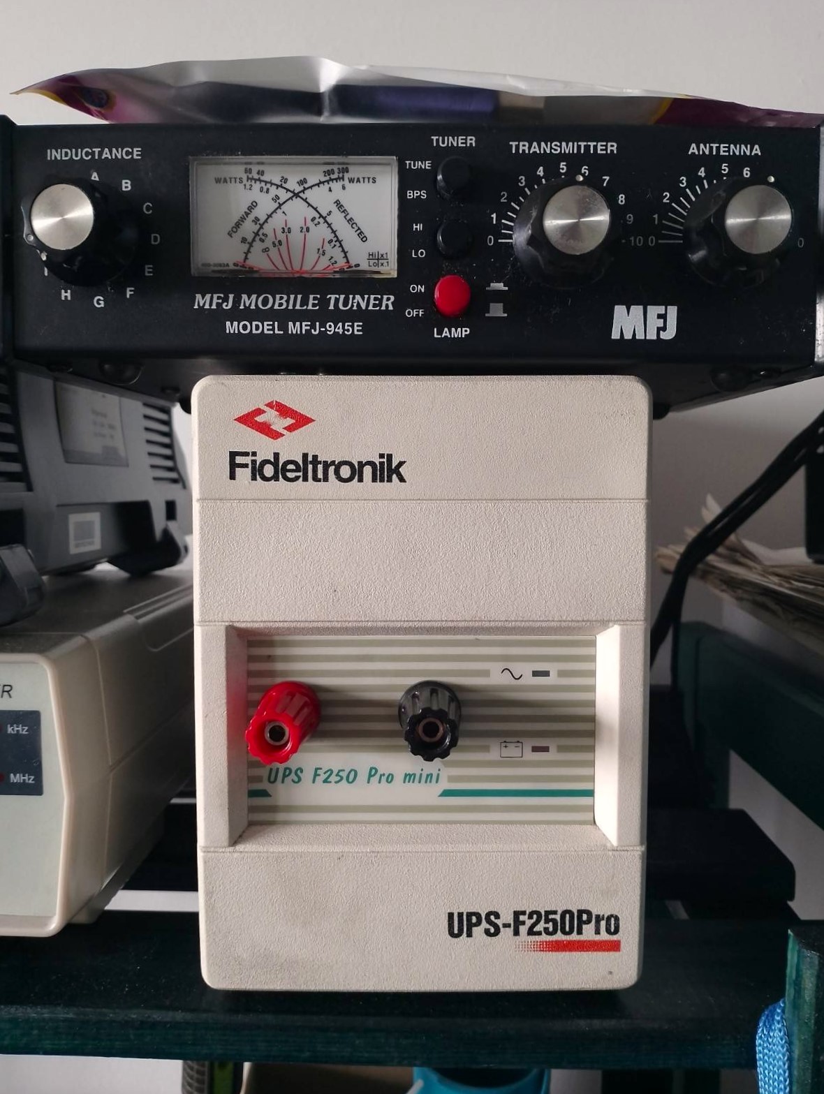
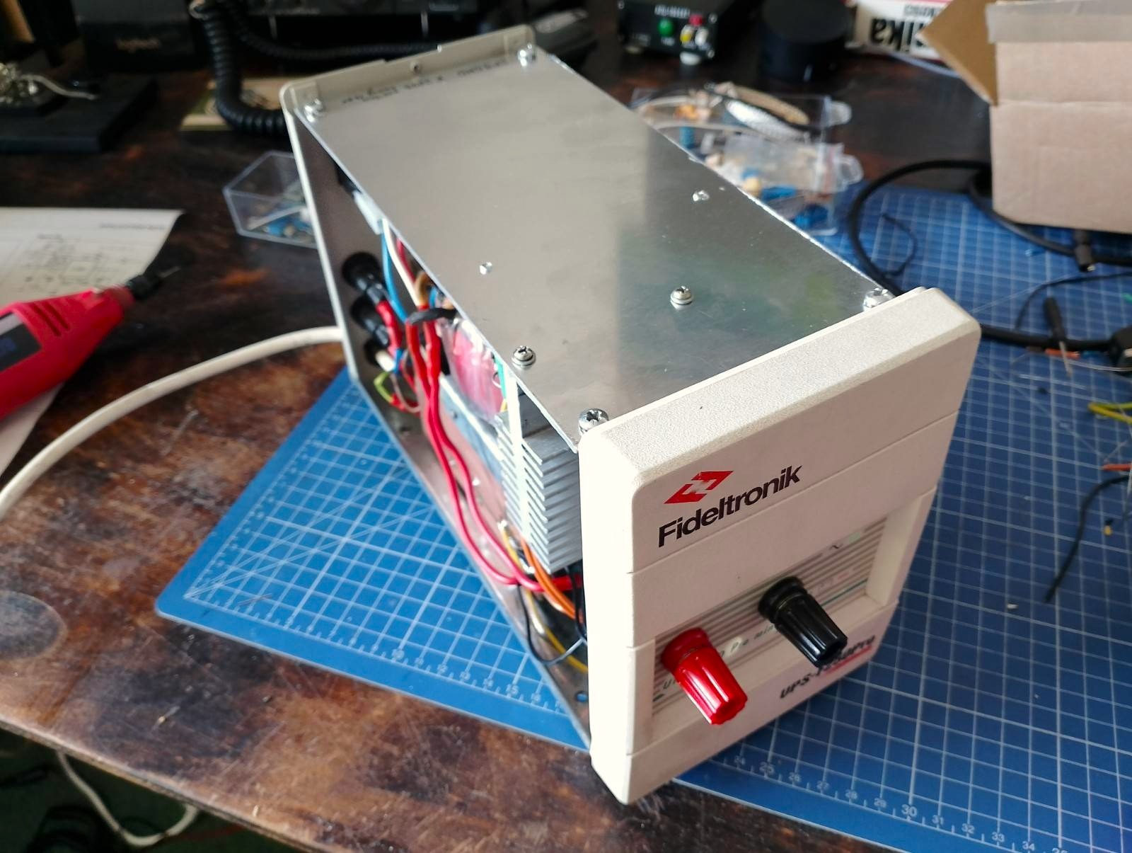
To relieve the aching back of my colleagues, I decided to build my power supply for the radio station, as cheaply as possible, but at the same time with overcurrent protection. I can’t afford to burn a radio with a makeshift power supply. One day I received old UPS from a friend of mine. The inconspicuous white box contained heat sinks, and a transformer and at the same time was suitable for a neat housing. So I had a great opportunity to build my own PSU.
Technical considerations
I spend a few days searching for IC suitable for a 15A power supply. Initially, I considered using LM350 + 3x2N3055, but I rejected this idea very quickly. Why? Because when using external transistors you can’t use internal overcurrent protection. So I quickly turned to uA723. However, I still haven’t found what I was looking for - the circuit designed with the old 723 is far more complex than the 3-pin stabilizer design copied from the datasheet. I was looking for something like LM350 - easy to use & reliable stabilizer but it must have the ability to connect an external shunt for overcurrent protection. Finally, I started reading about L200 and I hit the bull’s eye. It’s available in a Pentawatt enclosure and requires a minimal amount of components. Unfortunately, it’s no longer manufactured but you can buy NOS without much burden.
Design
This guide contains almost ready solutions. Creating first prototype didn’t take too long.
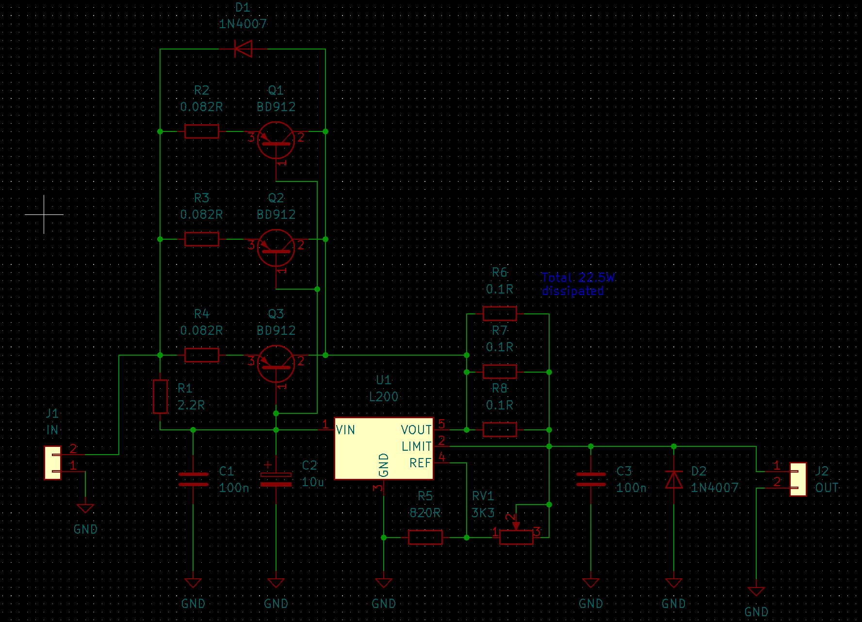
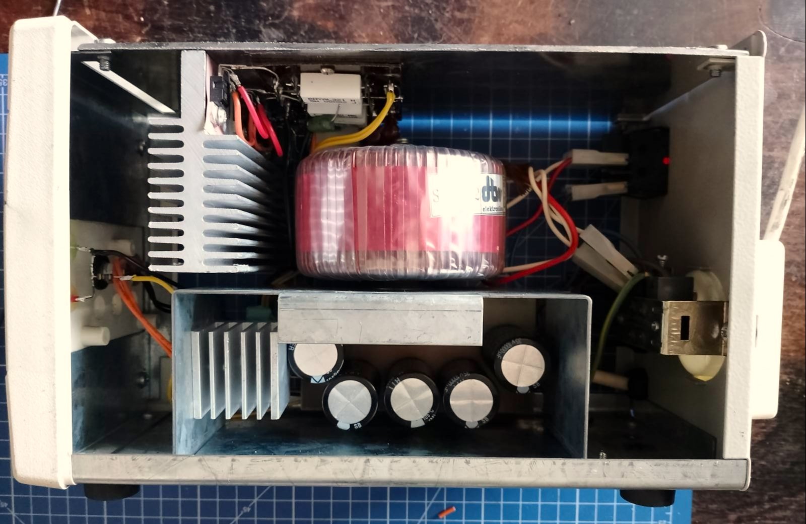
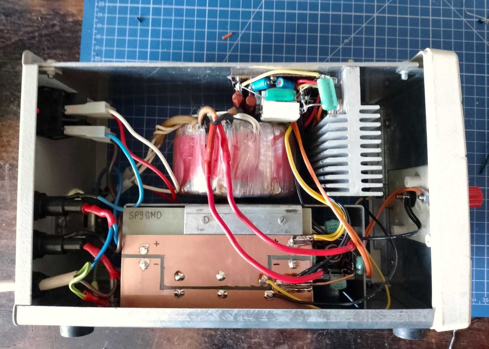
Those more perceptive will probably notice that my circuit is a combination of figures 28 and 29, and the transistors are connected in parallel using 82mOhm emitter resistors. I built my circuit using point-to-point connections with little help from a connector board used for vacuum tubes. The PCB visible in the lower part contains 5*10,000uF electrolytic capacitors and a 470Ohm resistor to discharge them. The rectifier bridge comes from the inverter welding machine and is able to work with a maximum of 20A current.
Conclusions
The power supply was tested under load in the form of two high-beam bulbs. It works as expected. I wouldn’t recommend using it for continuous work, but my radio is happy with this design!