Background
I haven’t built any ham radio transceiver in my life. I can’t recall any serious problems while recreating shortwave receivers, but I have never managed to add a transceiver and thus build proper ham radio gear. So I decided to start from a kit with technical support, well done, detailed manual, and simple architecture. I chose ILER-40 v3 by EA3GCY. Since the beginning I have been thinking about possible development, and here’s the reason why I bought a bare motherboard without recommended enclosure and AGC kit.
Package finally arrived!
I had to wait about 10 days for the package to be delivered. Do you want to see what I received? Parts are grouped into a few categories and every string bag corresponds to each category. The PCB was made using thick laminate. At this moment I realized that I received two linear potentiometers: one 50Kohm, and the second 10Kohm. The linear potentiometer is the wrong choice for an audio amplifier, but it can be replaced later.
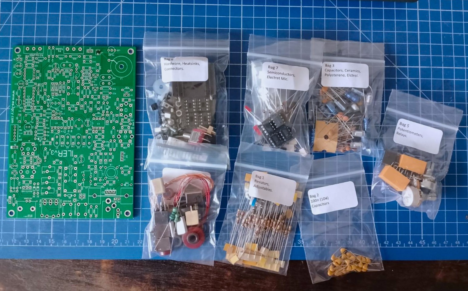
Javier’s accuracy deserves praise, I received an exact number of components, and that helped me find swapped elements. The assembly manual basically leads you by hand, but I recommend tunning LC filters using VNA instead of tunning them for max volume or max output power.
First test
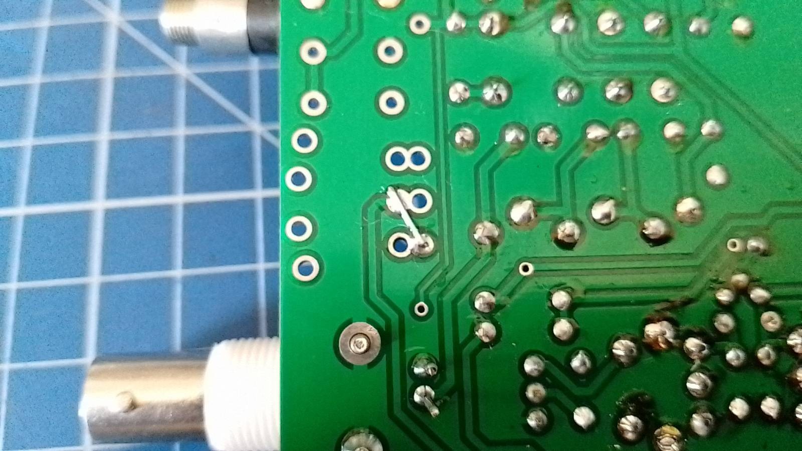
Ok, here the fun begins. After finishing soldering all parts, and tunning filters with NanoVNA I decided to connect the power. I was surprised because I haven’t heard anything from the headphones. Touching LM386’s inputs with a screwdriver haven’t changed anything so I decided to check the traces on the board and I realized that without soldering the external speaker/headphones switch I need to add a small jumper. You can see it in the foto below.
The problem
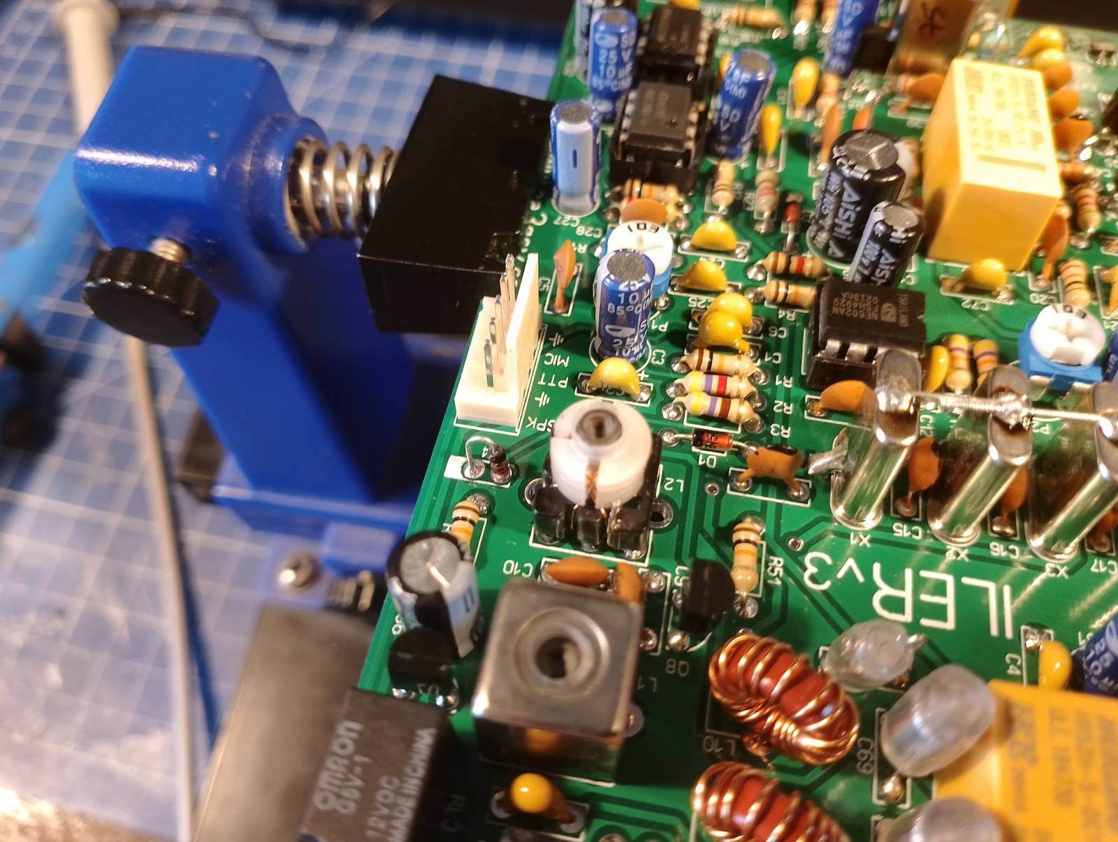
Do you know what’s more interesting? After fixing this small error I heard a noise in the headphones, but the radio didn’t respond to connecting an antenna. I took a screwdriver and I began touching different parts of the circuit with it. The AF amplifier was working perfectly, AF filter too. By touching the input of a second mixer I was able to hear Radio Romania, and the radio responded with a small crack sound for touching the first mixer input. It suggested some problems with the input filter. So I took an ohmmeter and I started measuring TOKO-like canned coils and…. bingo! They had broken windings.
The solution
I wouldn’t wish desoldering those filters to my worst enemy. After a long fight, I had to open cans to fix a winding. I did that by simply prying a metal can with a small knife. The damage could be seen easily. After short consideration I decided that there was no point in rewinding broken coils, then I fixed them with small pieces of wire as you can see below. After resoldering filters, I could hear noise increasing when connecting an antenna and I was able to pick a few CW stations. Great! It was a good moment to add a digital frequency readout.
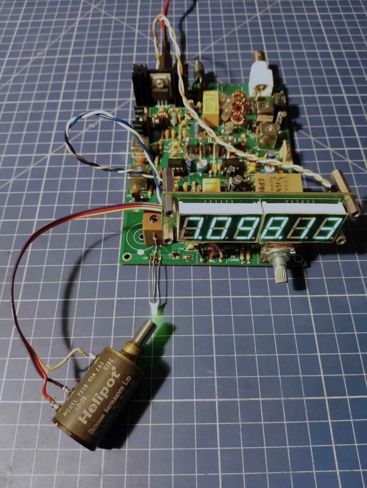
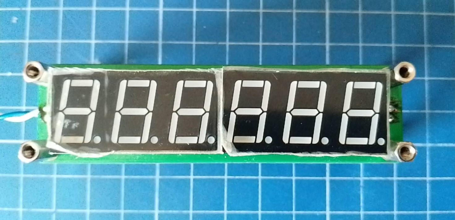
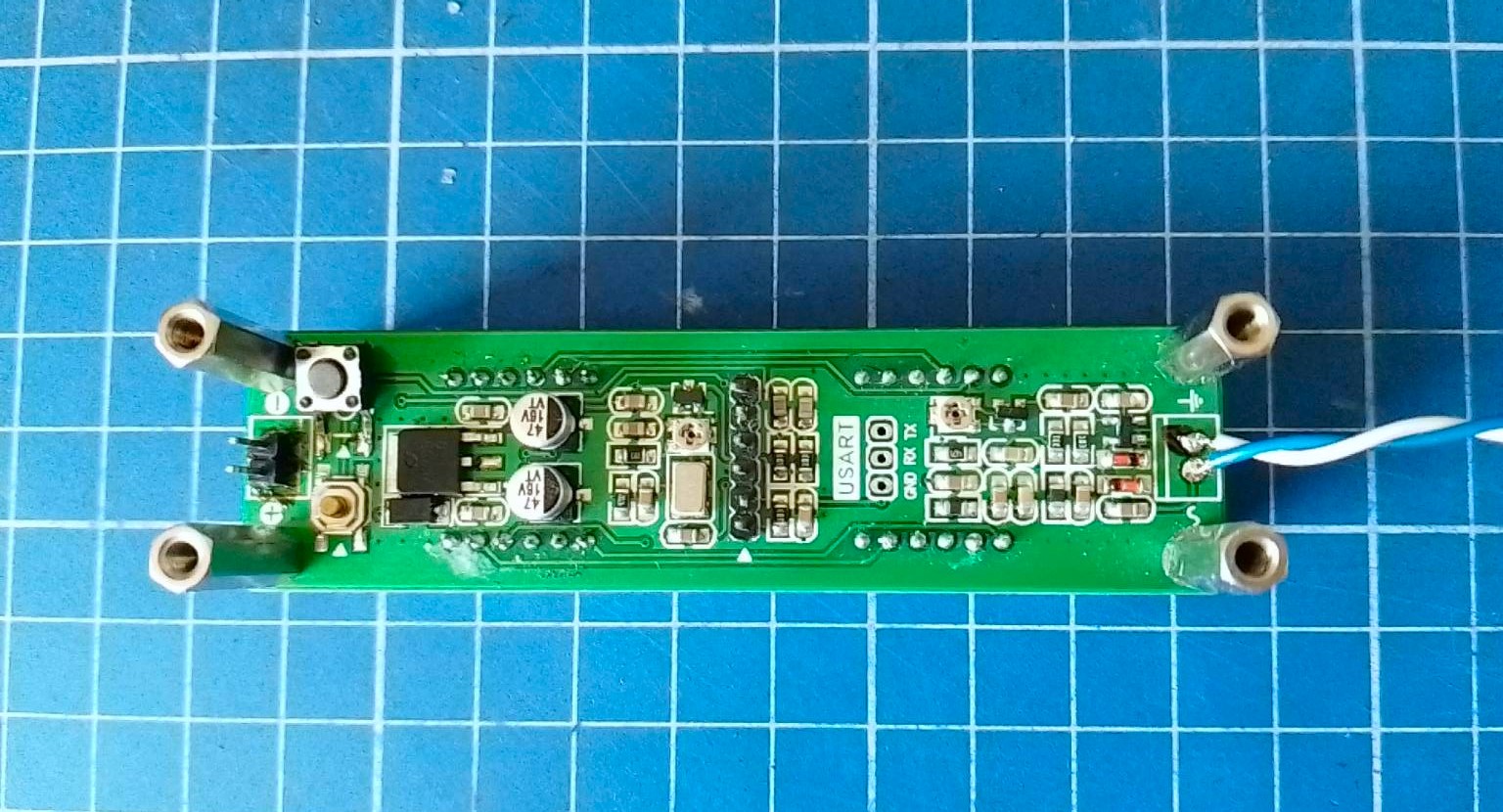
Frequency counter
I remembered I had a Chinese frequency counter in my junk box. I was right, I had to replace the broken tact switch with some from the broken VCR and it worked like a charm. I programmed IF frequency subtraction and since this moment I didn’t have to calculate ILER’s frequency.
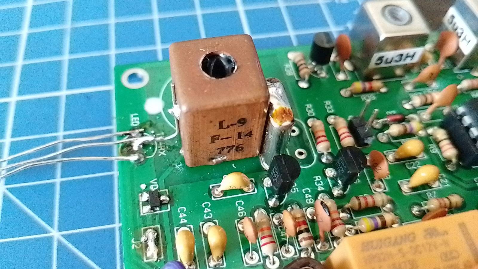
VXO fix
I had to set the VXO frequency range with the coil and I would be done. It turned out very quickly that compressing and decompressing turns constantly is only for the faint-hearted. So I replaced the Amidon core coil with a random IF filter from some old radiotelephone which had about 17uH (adjustable) and I soldered shielding to the crystal enclosure, then I grounded the whole part. It eliminated the effect of bringing your hand closer to the radio. With the original coil, it detunes about 2KHz when you approach the motherboard with your hand.
AGC board
It was enough that Sasha from Moscow called a friend with a power of 5kW, and I almost went deaf. So I decided to design the AGC board based on the original schematic but with SMD parts only.
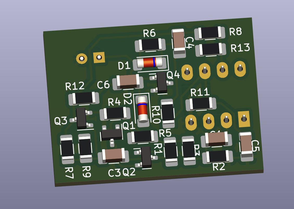
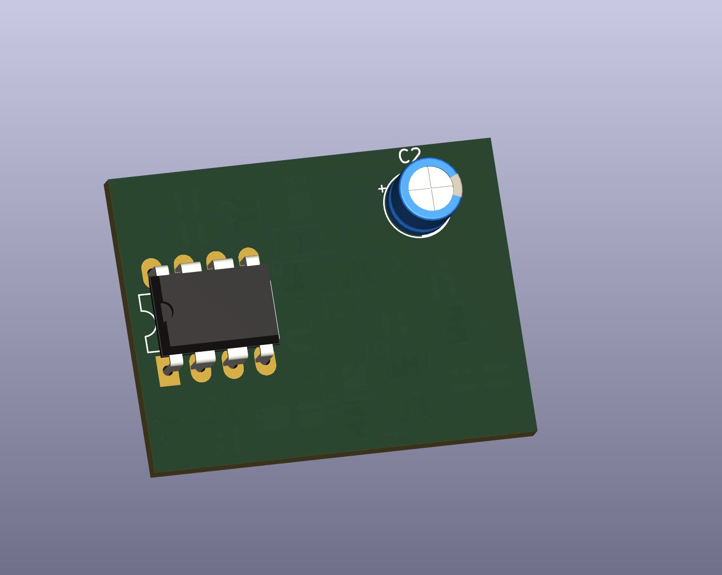
I made the mistake of not using the hand solder footprint for the transistors but somehow managed to solder it. I will share the PCB design together with the documentation of the completed radio. Keep in mind that you have to remove C28 and R14 instead of R17 and C31 while installing it in V3 version. It seems like AGC was designed for older ILER review. The circuit works well, but in my opinion, the output level is not enough, I will try to adjust the values of the elements to get the desired volume. In addition, I changed the value of the electrolytic capacitor responsible for the AGC time constant to a lower value, because the original was too slow.
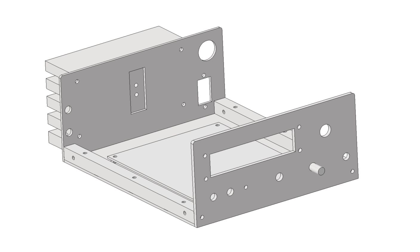
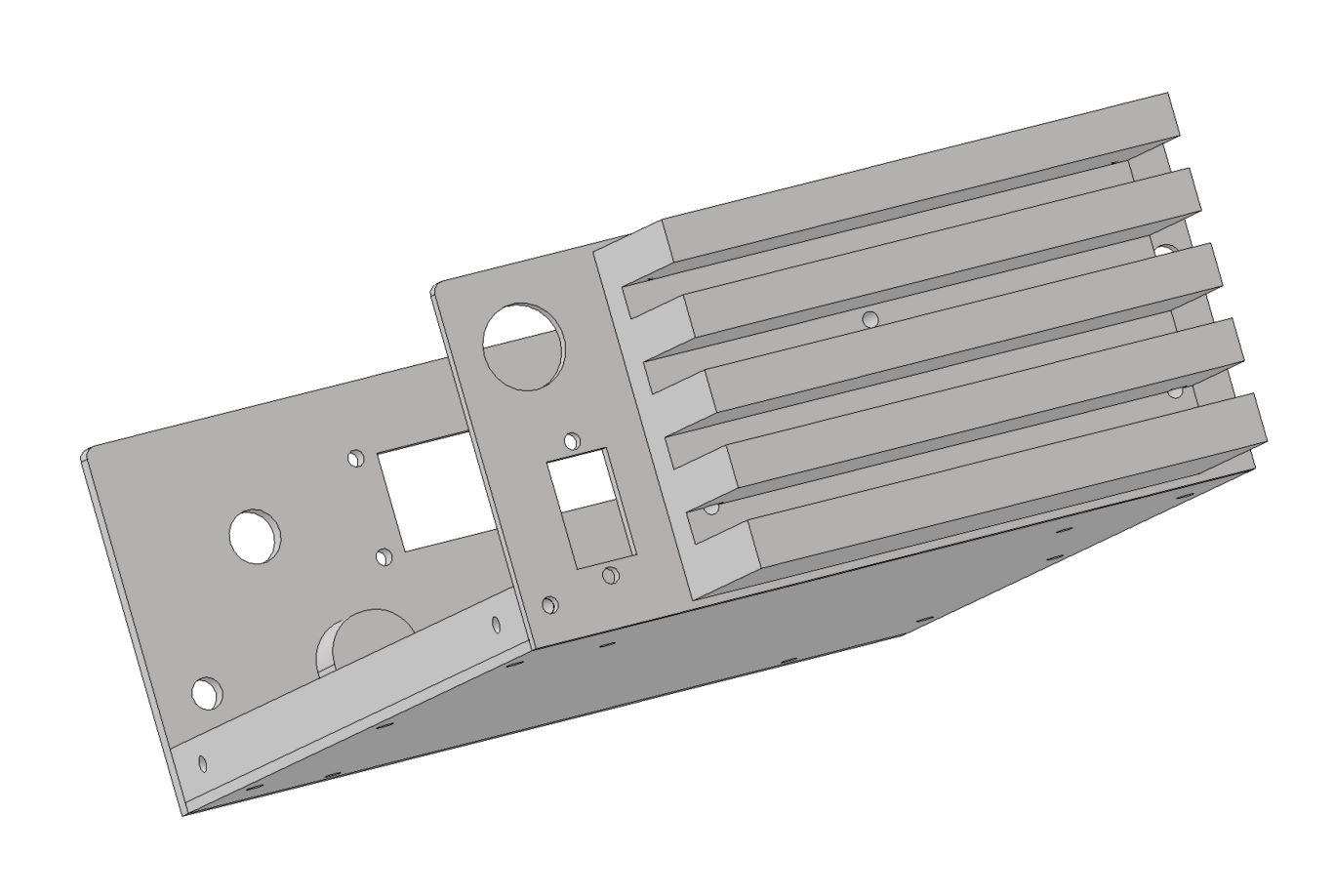
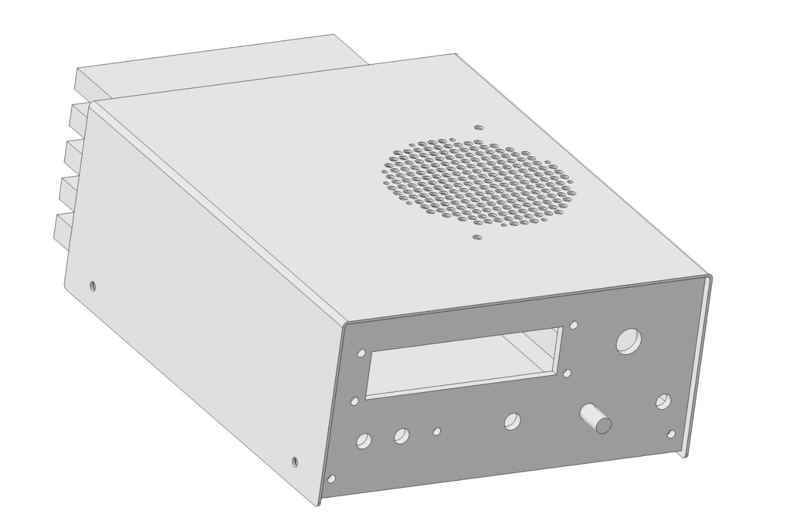
It’s housing time!
With the radio running, I decided to design a housing for it. The project was created in Autodesk Inventor. I will share the .ipt files after checking everything fits together. The housing consists of several pieces of sheet metal that are easy to cut with a laser and two sections of a 10x10mm structural profile. The structure will be powered by the XT-60 connector. In the housing, I have provided space for a 30W power amplifier for 2xIRF530 and a low-pass filter.
Summary
Trasceiver works as expected, It has 6W SSB output power. I will measure the sensitivity soon. That’s it for now, I’m waiting for laser-cut elements, and in the next article, I will describe the further history of the construction - the activation of the Chinese PA 30W and tuning the low-pass filter.