Background
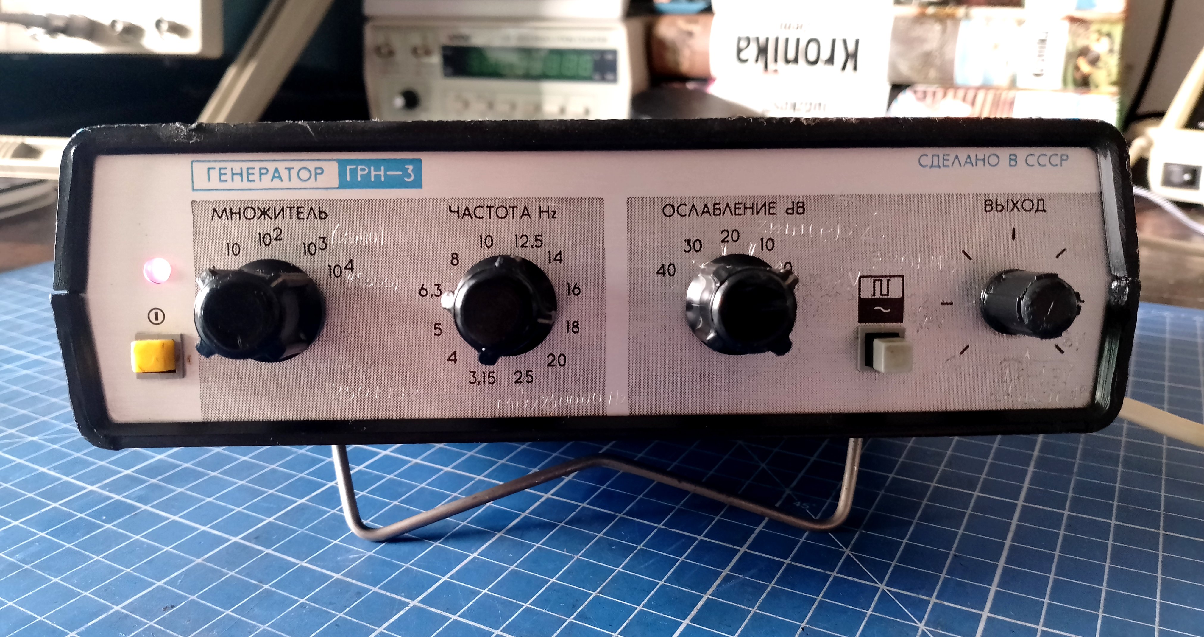
Soviet electronics always contained some unusual solutions. Despite its poor quality I find tearing Russian devices very entertaining. That’s why I decided to show you the interior of this low-frequency generator.
The front panel design reminds me of the C1-118 & C1-112 oscilloscopes. It’s a shame that the generator has a different width than those scopes because it would create a really nice set.
Enough talking, let’s tear it down!
Ah, the quality of Russian electronics…
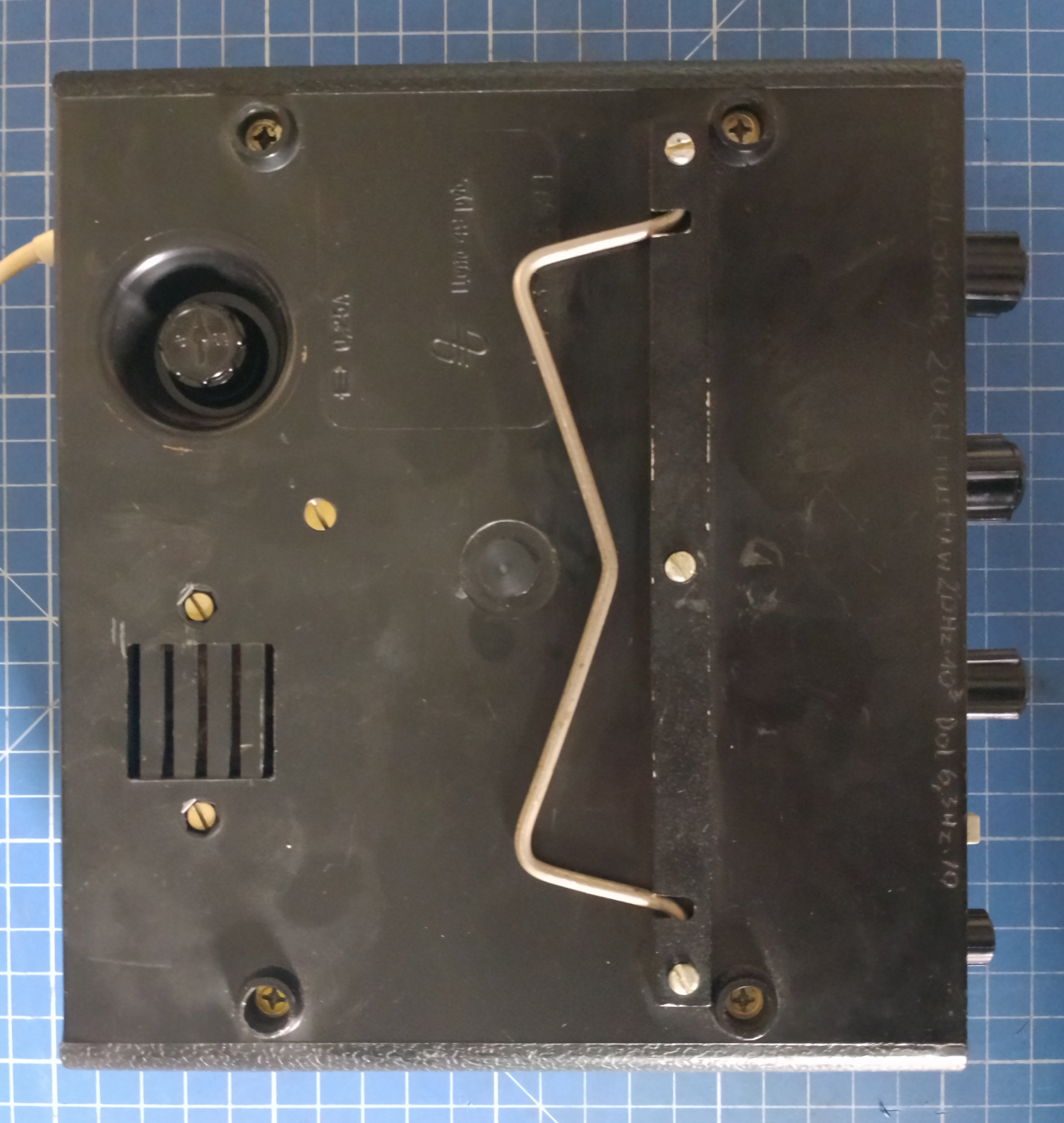
Both parts of the enclosure are so supple that you can bend them easily. The plastics don’t fit together, putting them together is almost a miracle.
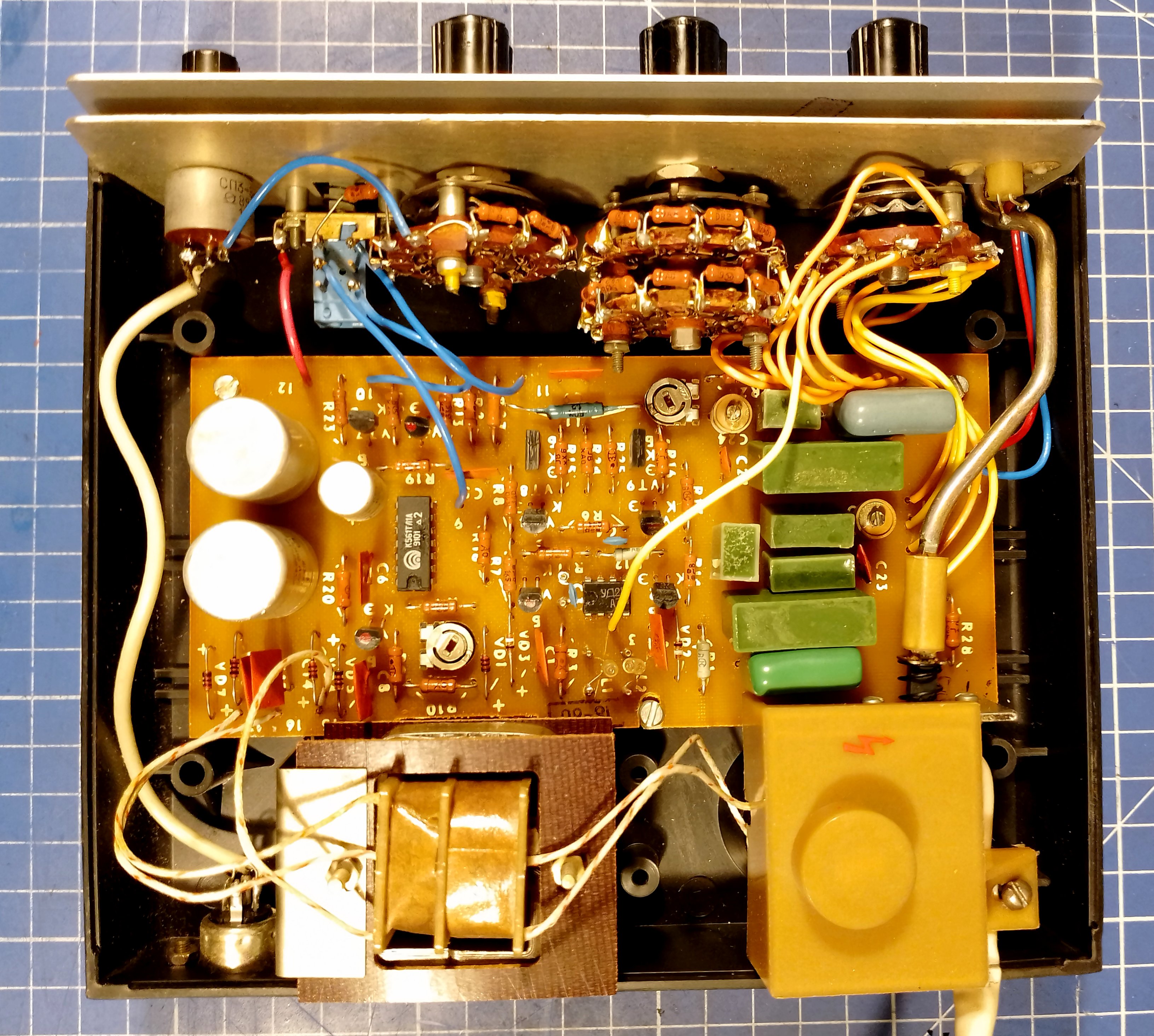
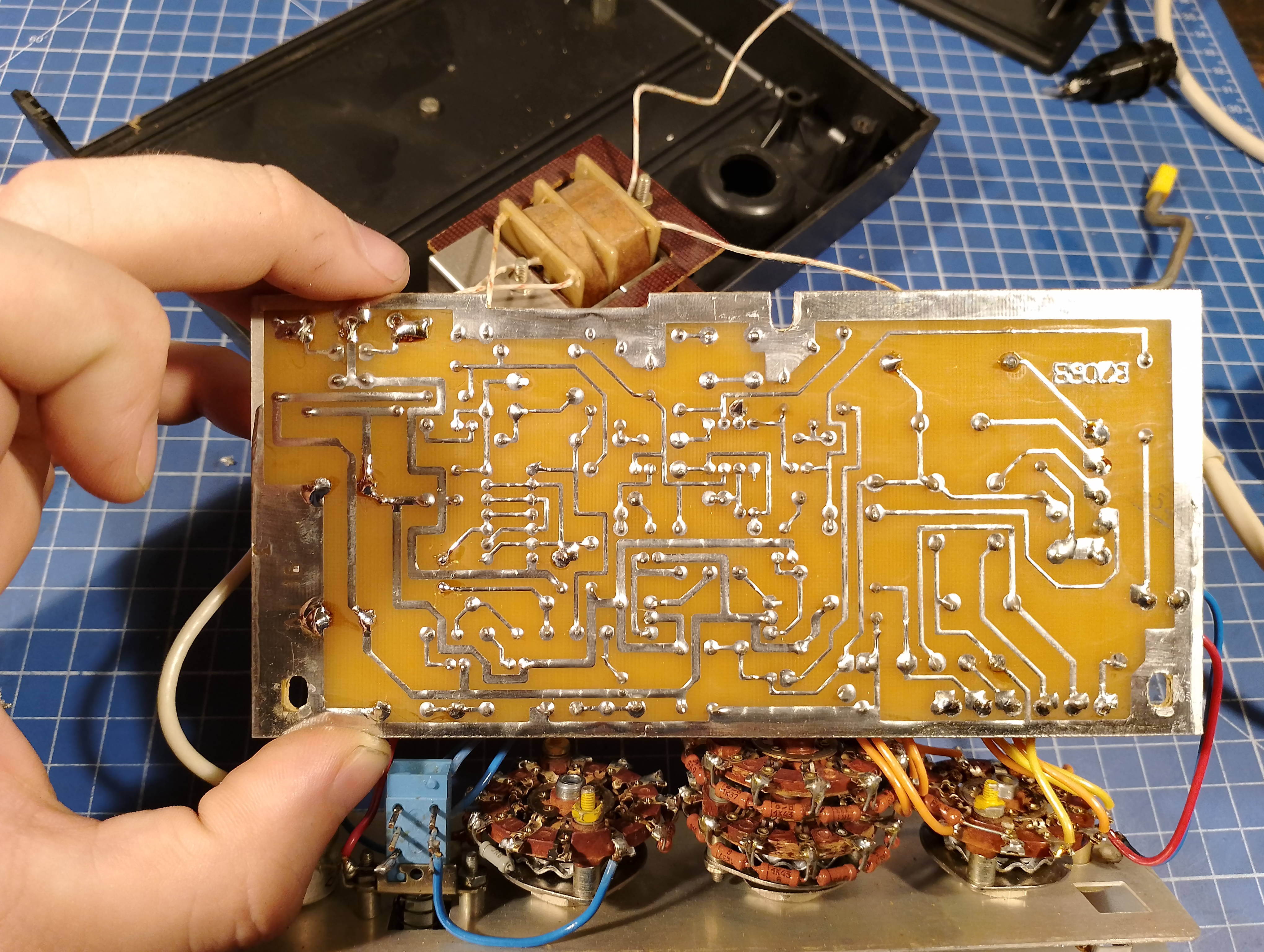
After opening we can see entire device build on single PCB.
I decided to blindly replace the electrolytic capacitors, because I know that the Russian capacitors were of terrible quality.
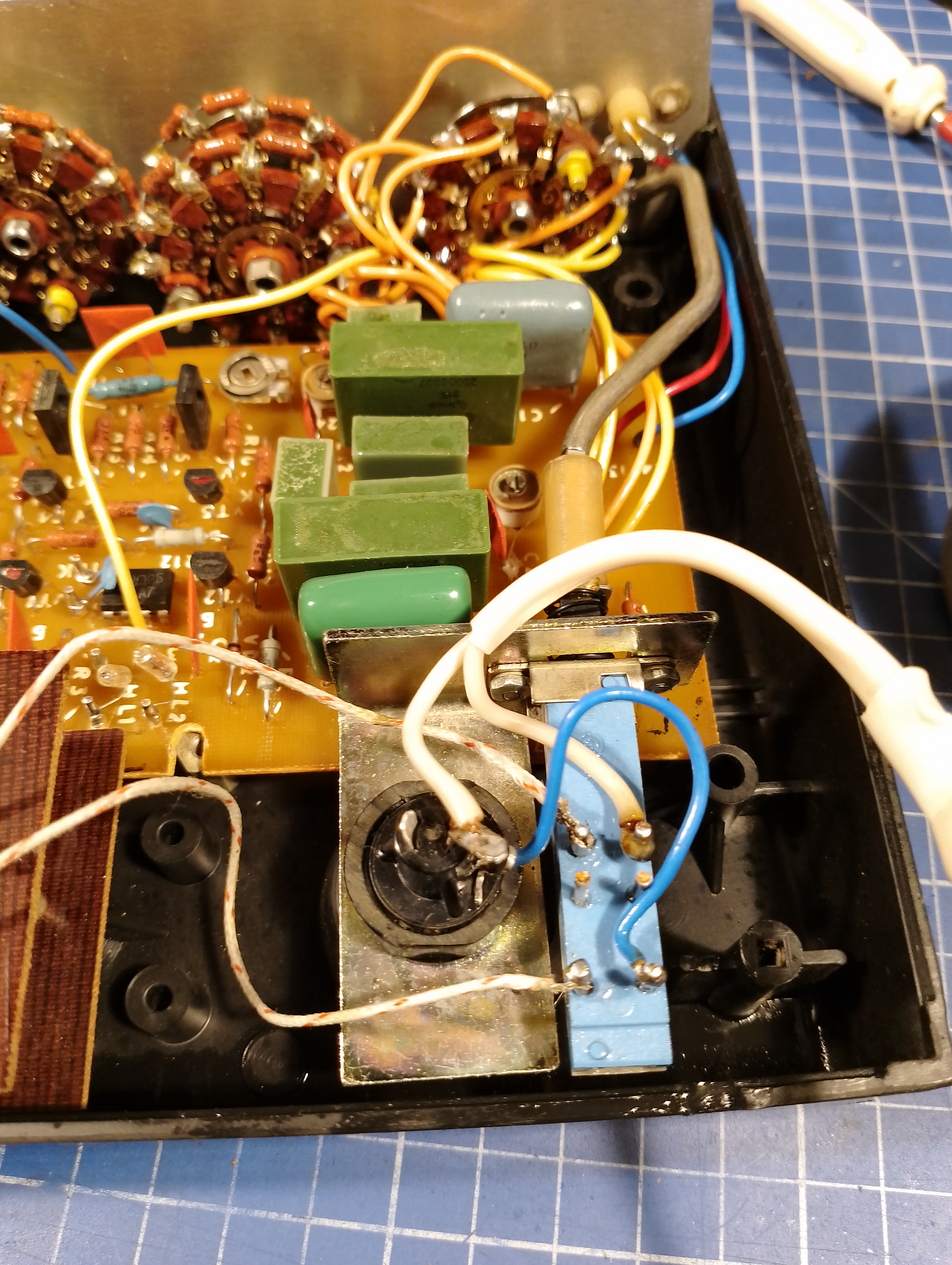
I took off the plastic cover of the mains switch for a moment to see what was under it. I saw very poorly soldered wires that were about to break off. I repaired the connections with some fresh tin, because the whole thing posed a threat to the user’s life.
Repair
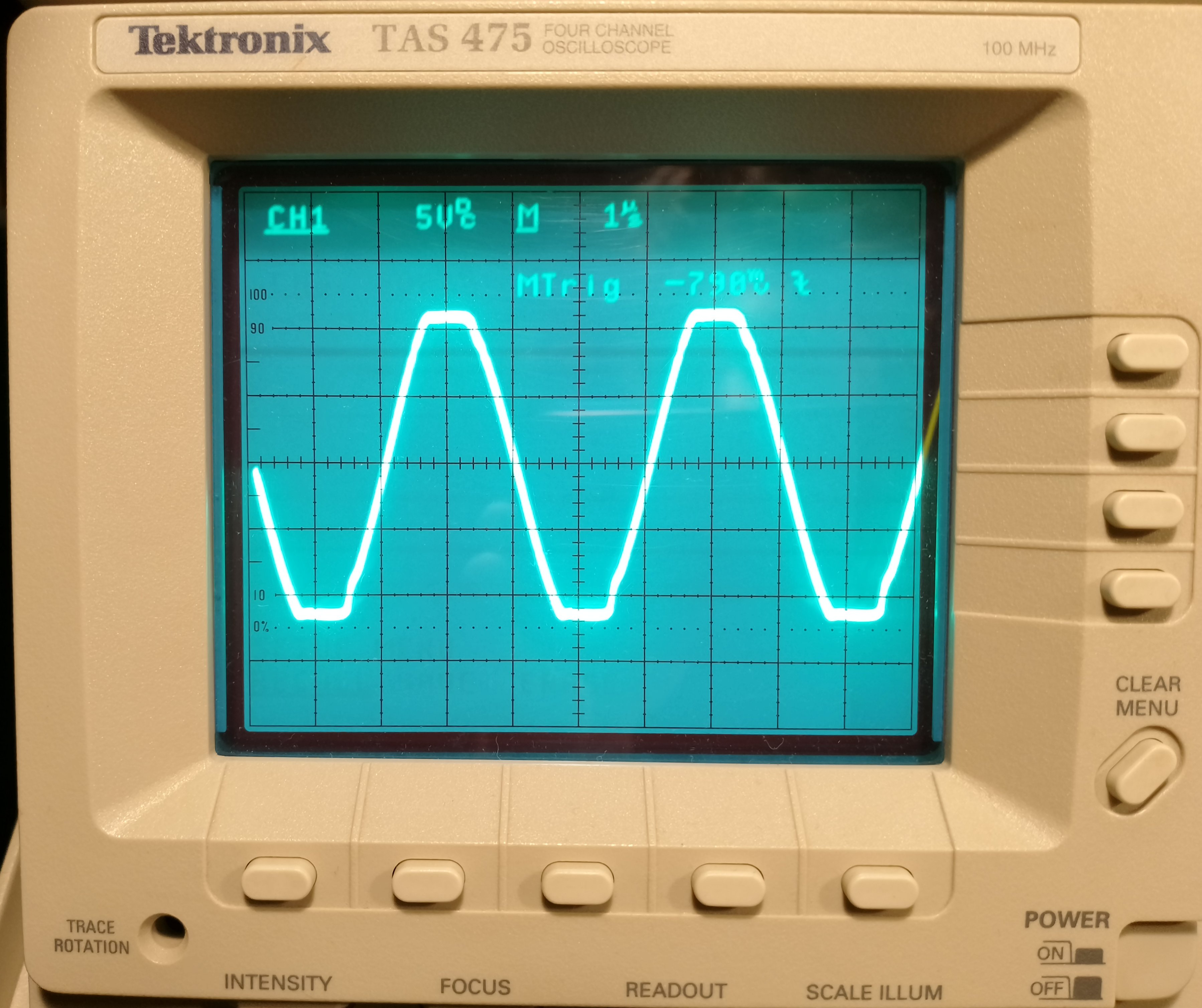
Well, since I managed to deal with the most serious faults, I decided to check the quality of the signal from the generator. As you can see in the oscillogram, the sine wave had its peaks cut off.
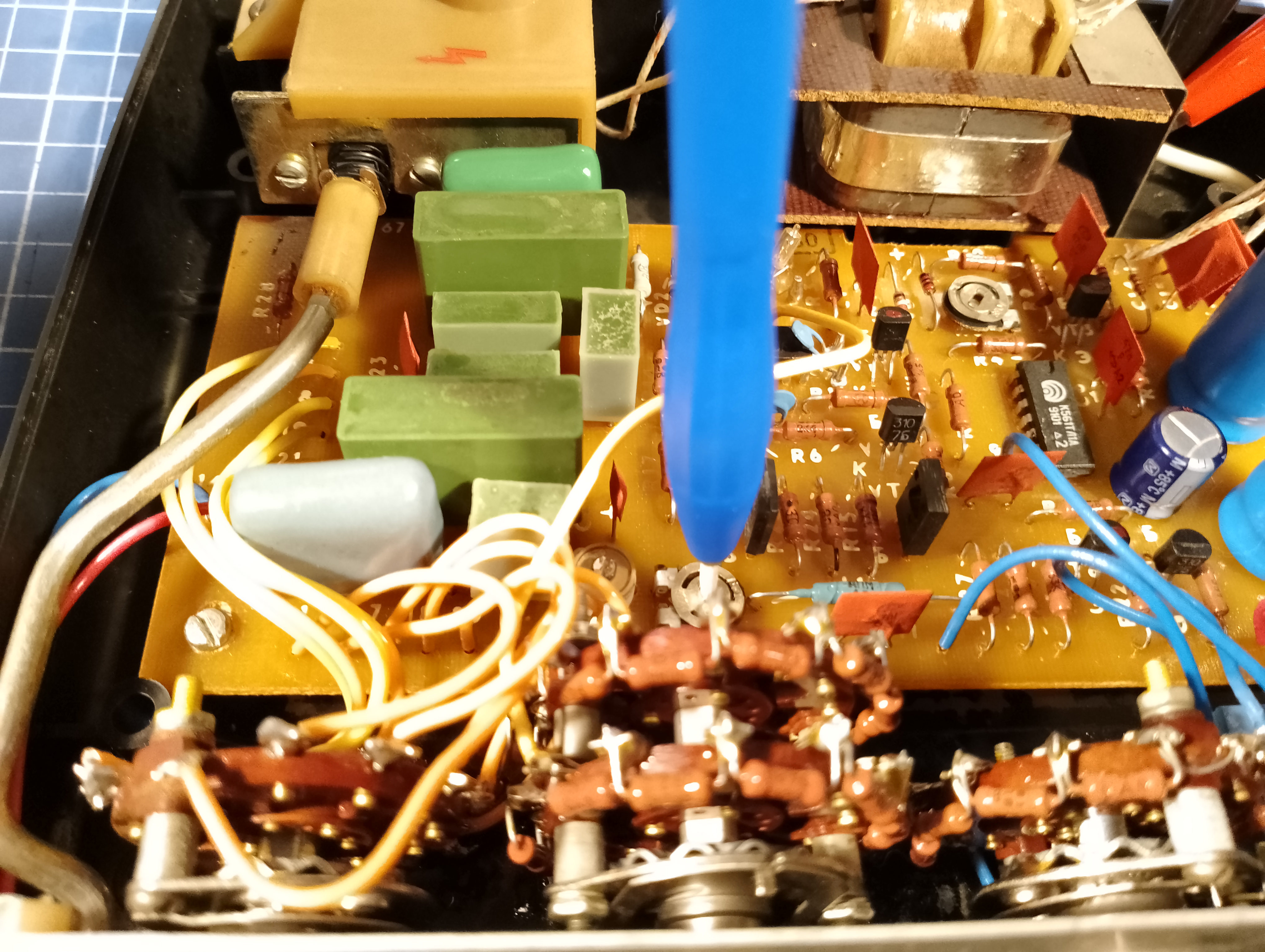
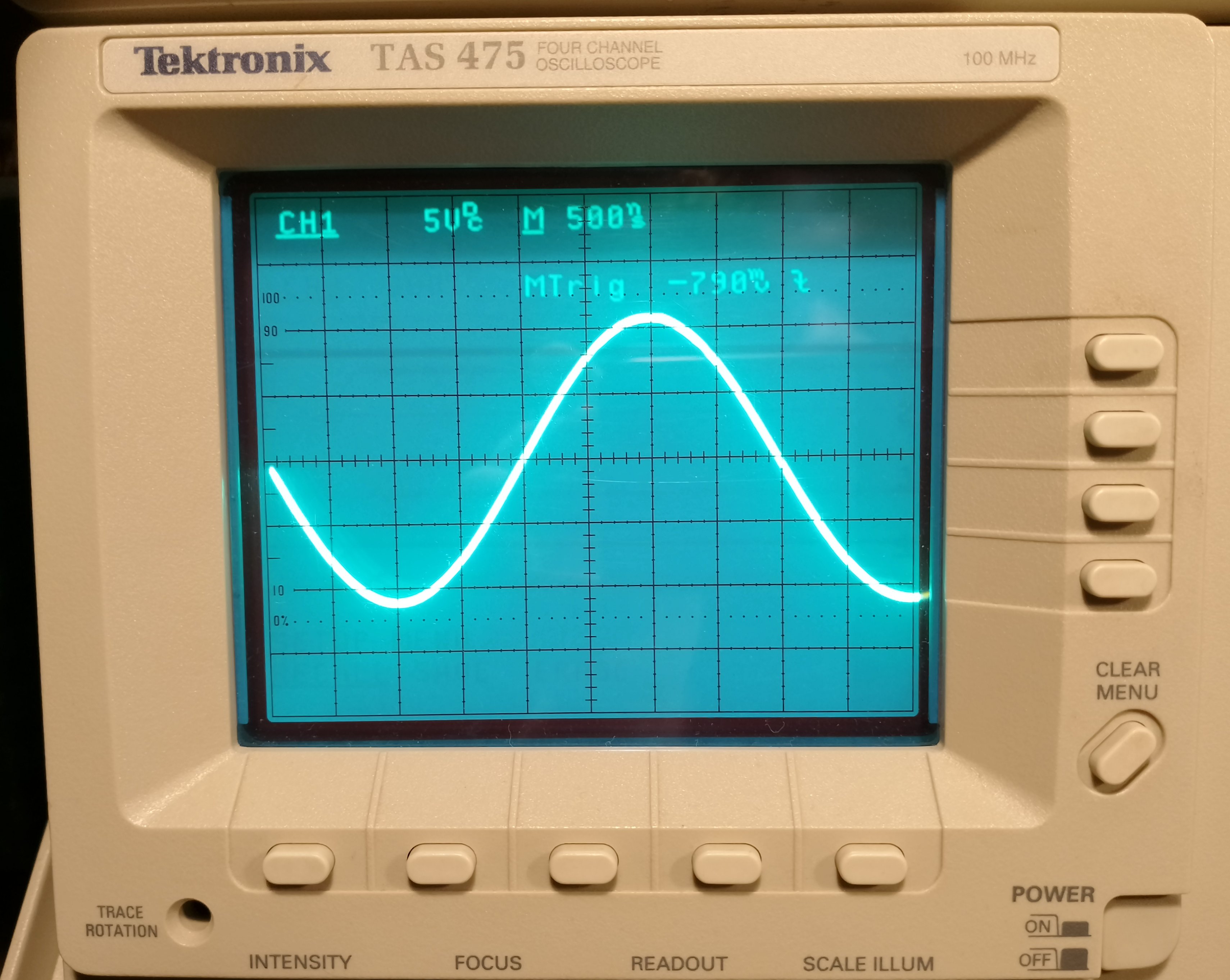
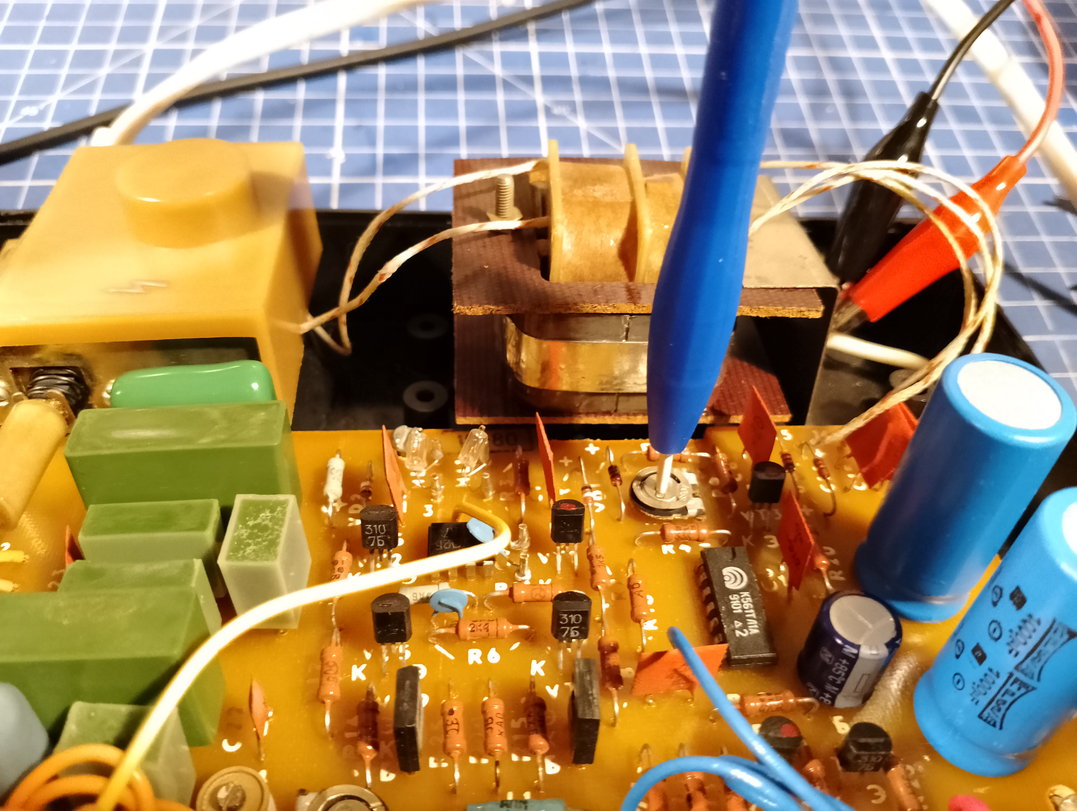
Fortunately, it turned out that the designer had included a potentiometer on the board to set the operating point of the signal amplifier, which made it possible to easily correct this defect.
Calibration
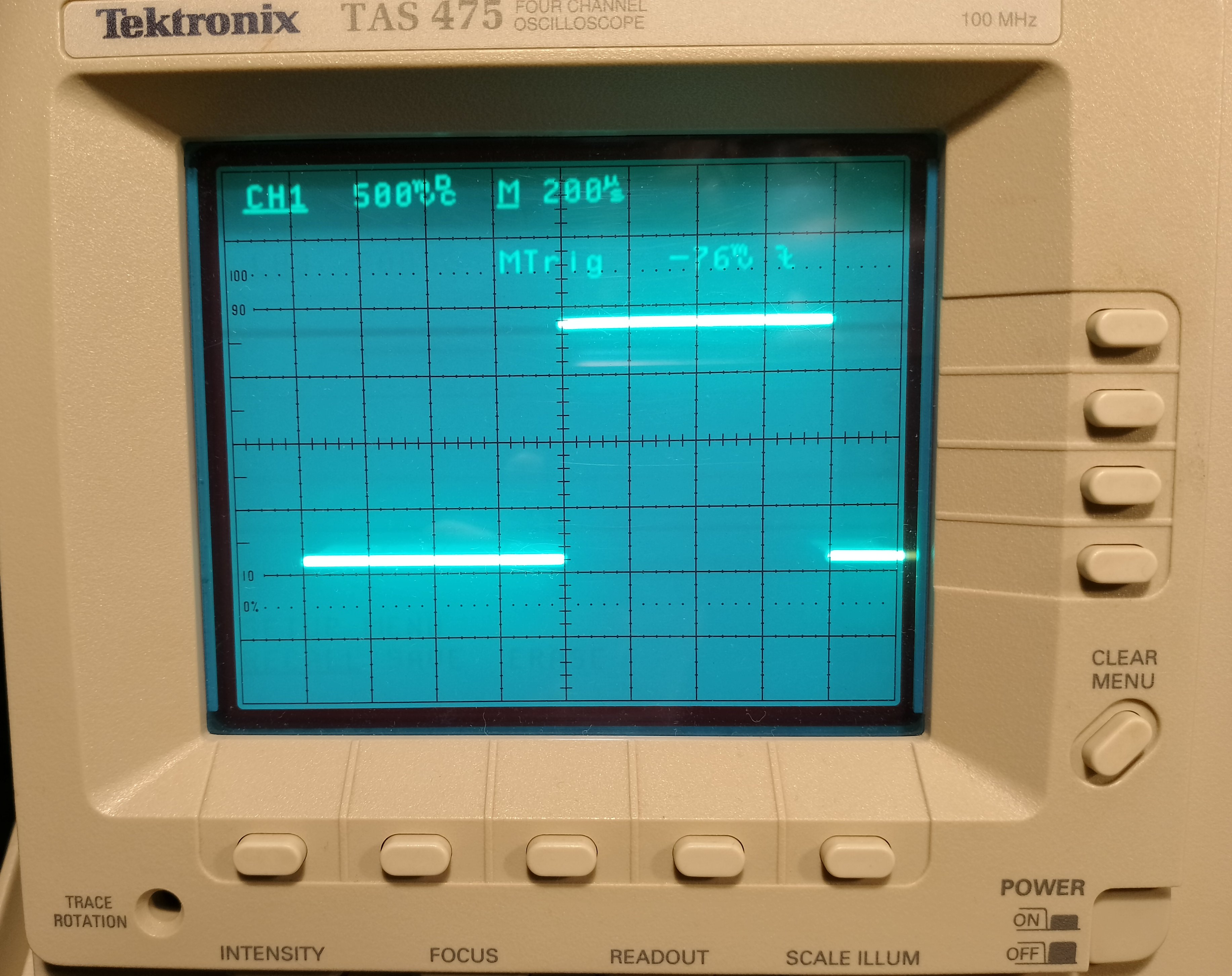
Additionally, I decided to set the duty of the rectangular waveform to 50%.
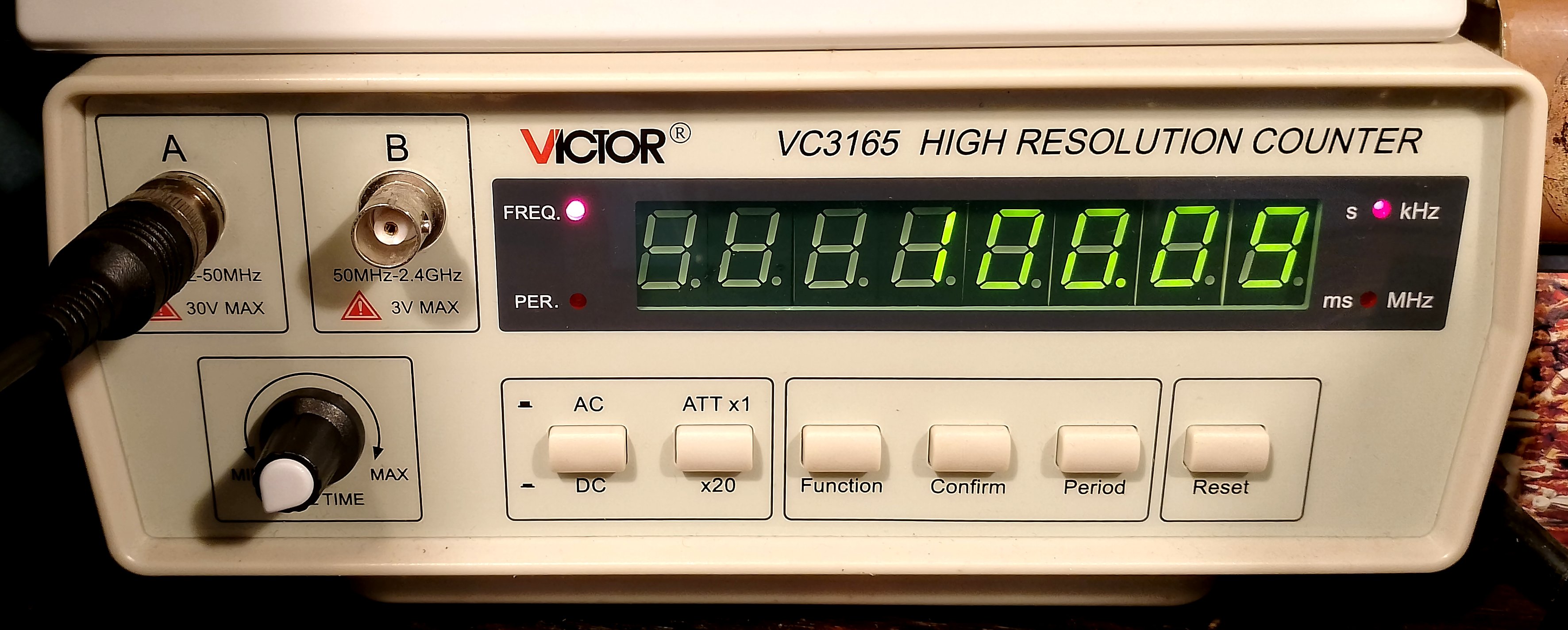
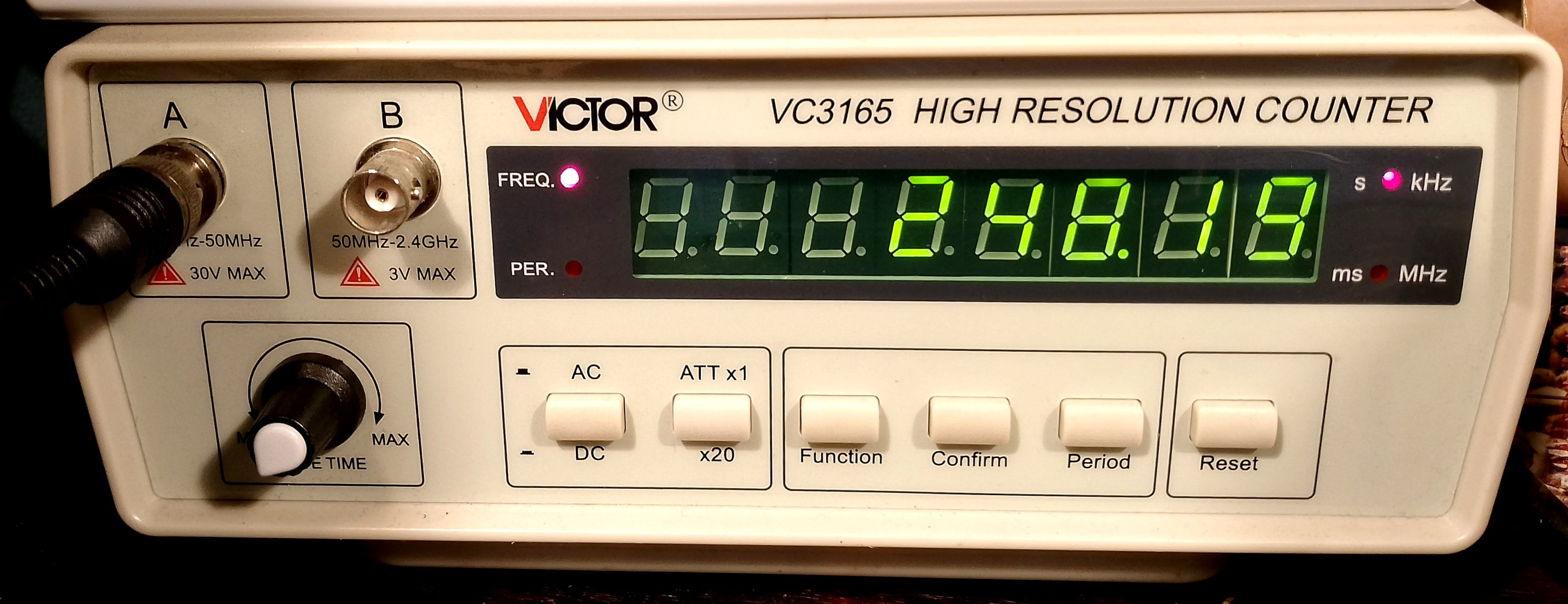
The generator frequency is selected in steps. We choose the frequency basis and the multiplier. I calibrated the device so that the frequency set by the switches coincided with reality.
Summary
Nowadays, the parameters of this generator are not impressive, but it can still be used to test audio devices.
