Introduction
Many electronics engineers prefer digital oscilloscopes over analog ones. Considering that a digital oscilloscope allows for easy measurement of frequency, RMS value, and many other parameters without the need for mental calculations, it is understandable. However, an analog oscilloscope remains invaluable for the investigation of analog-to-digital converters as it enables the detection of any “steps” in the analyzed signal.
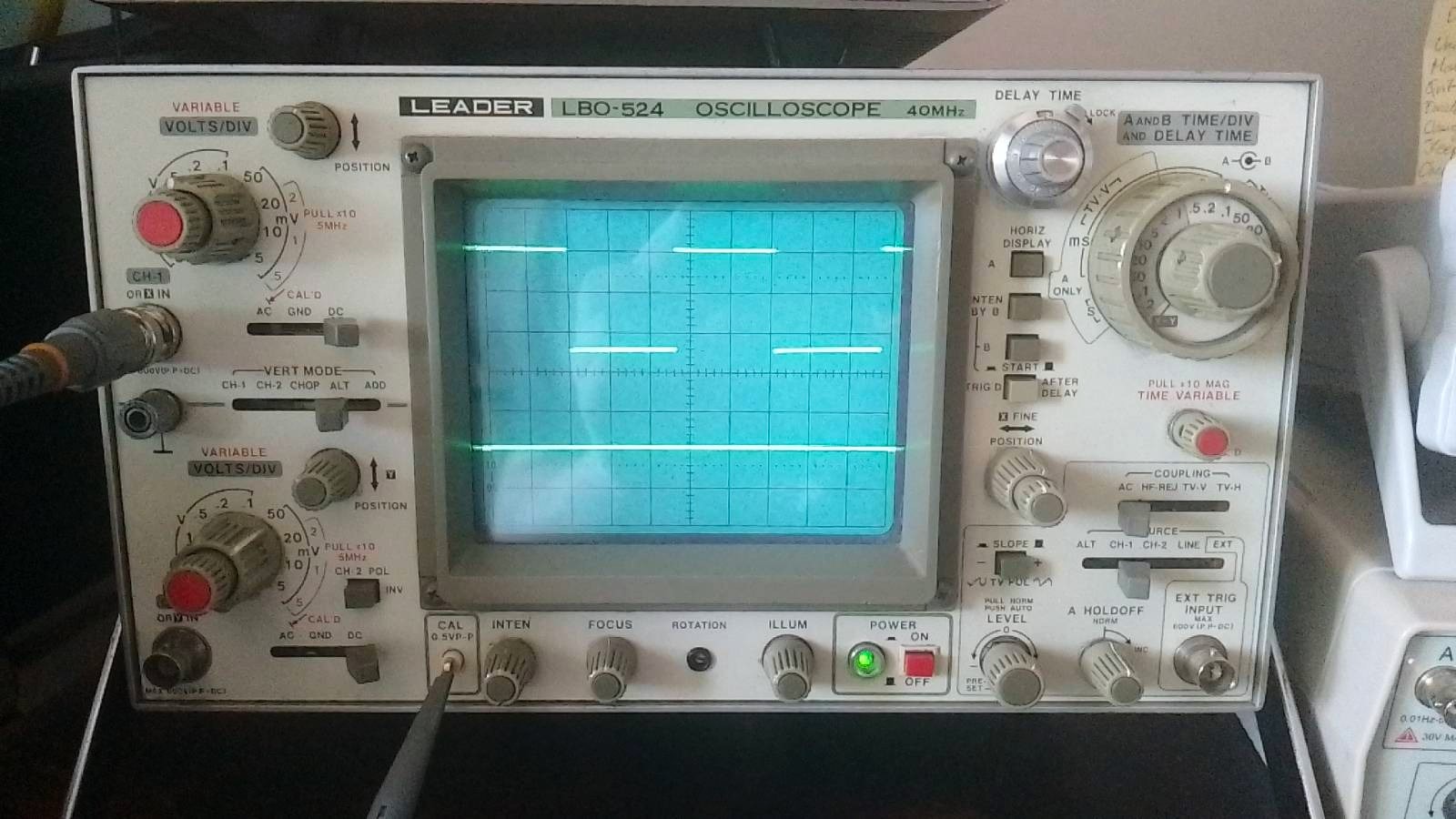
I bought this oscilloscope as a bargain from a guy who sold measuring equipment imported from Switzerland. I made a blind purchase, even though I could accidentally buy equipment with a burnt-out lamp. It turned out that the oscilloscope was so little used that it even had a protective film on it!
My “old man” works quite well, but for some time now a switch was interrupting, and this knob was creaking … It forced me to disassemble the oscilloscope and thoroughly clean it. By the way, I decided to take pictures, because this model is not very popular and I have not found pictures of its interior on the Internet. Let’s start!
We look inside…
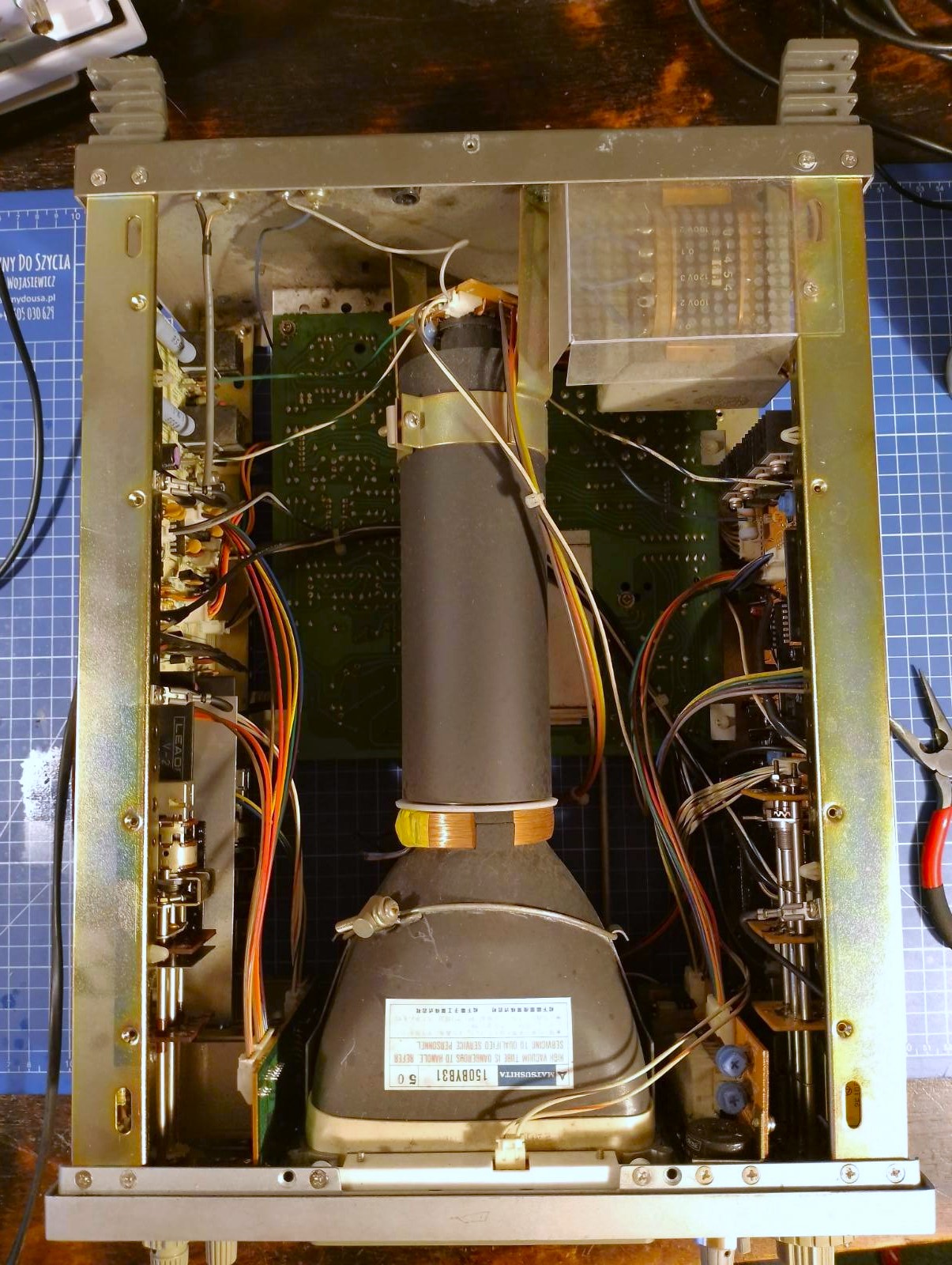
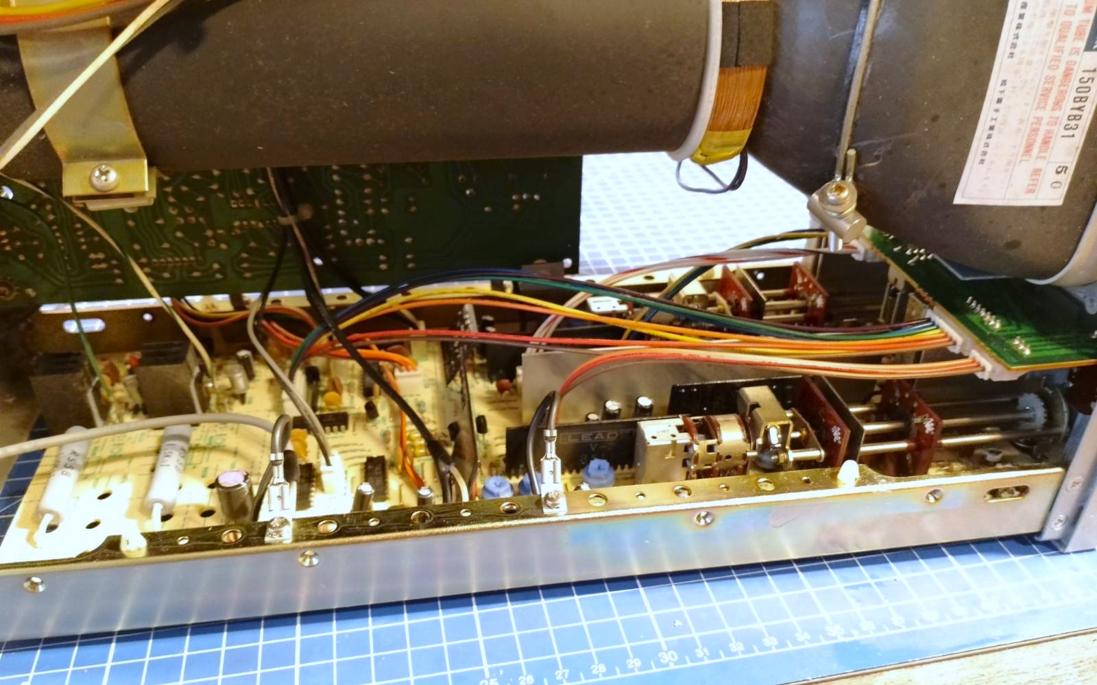
After removing the top cover, an oscilloscope lamp appears in front of our eyes. On the left, you can see the Y amplifier board, on the right is the horizontal deflection board. A fairly small mains transformer is visible in the upper right corner. The manufacturer covered it with a protective cover. In fact, it doesn’t do much, because we can still touch any of the lamp pins where there are high deflection voltages. But at least we will die electrocuted from a source separated from the mains :wink:
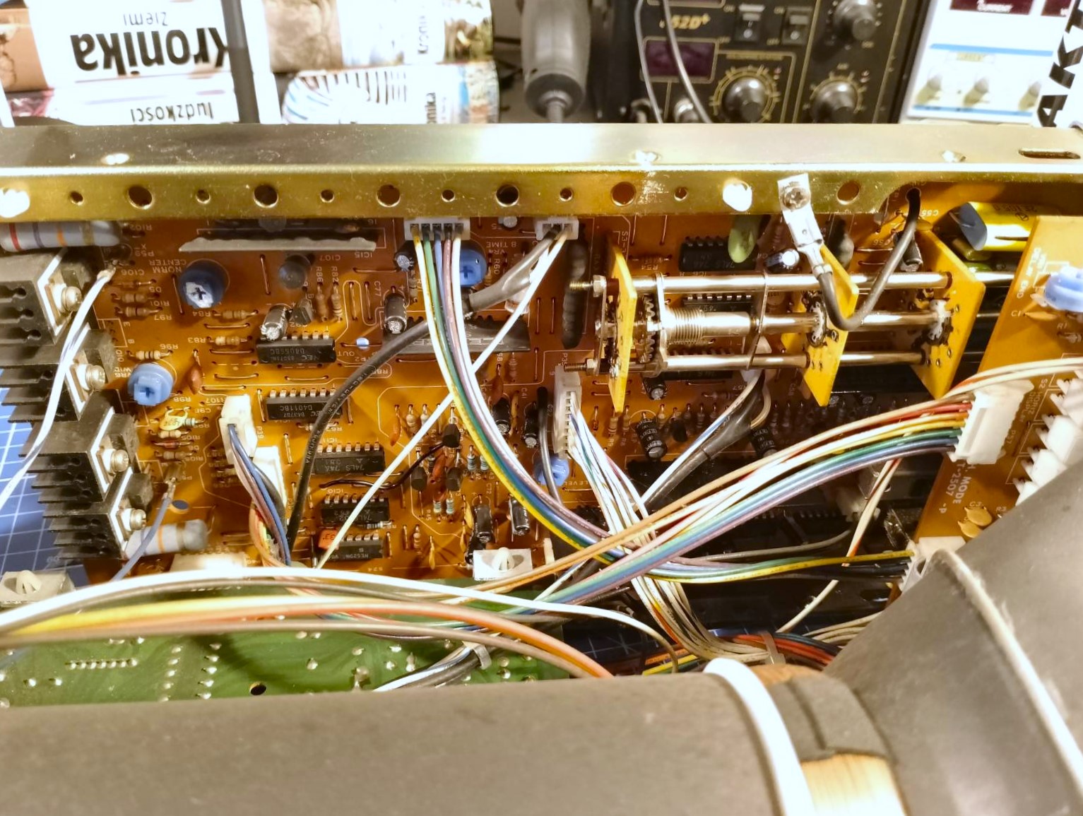
After removing the bottom cover, we can see the power supply board on which there are also circuits that determine the working conditions of the lamp: focus control, backlight brightness, brightness.
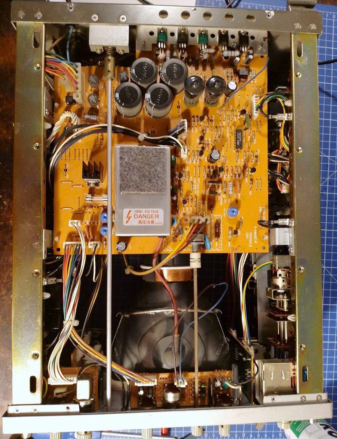
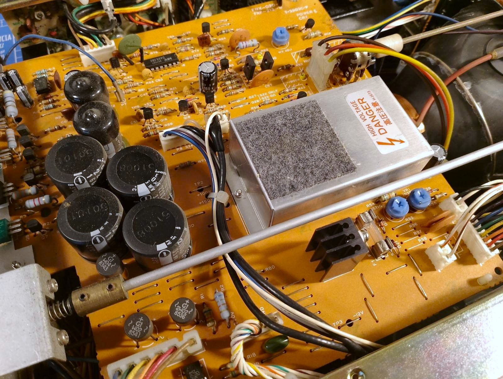
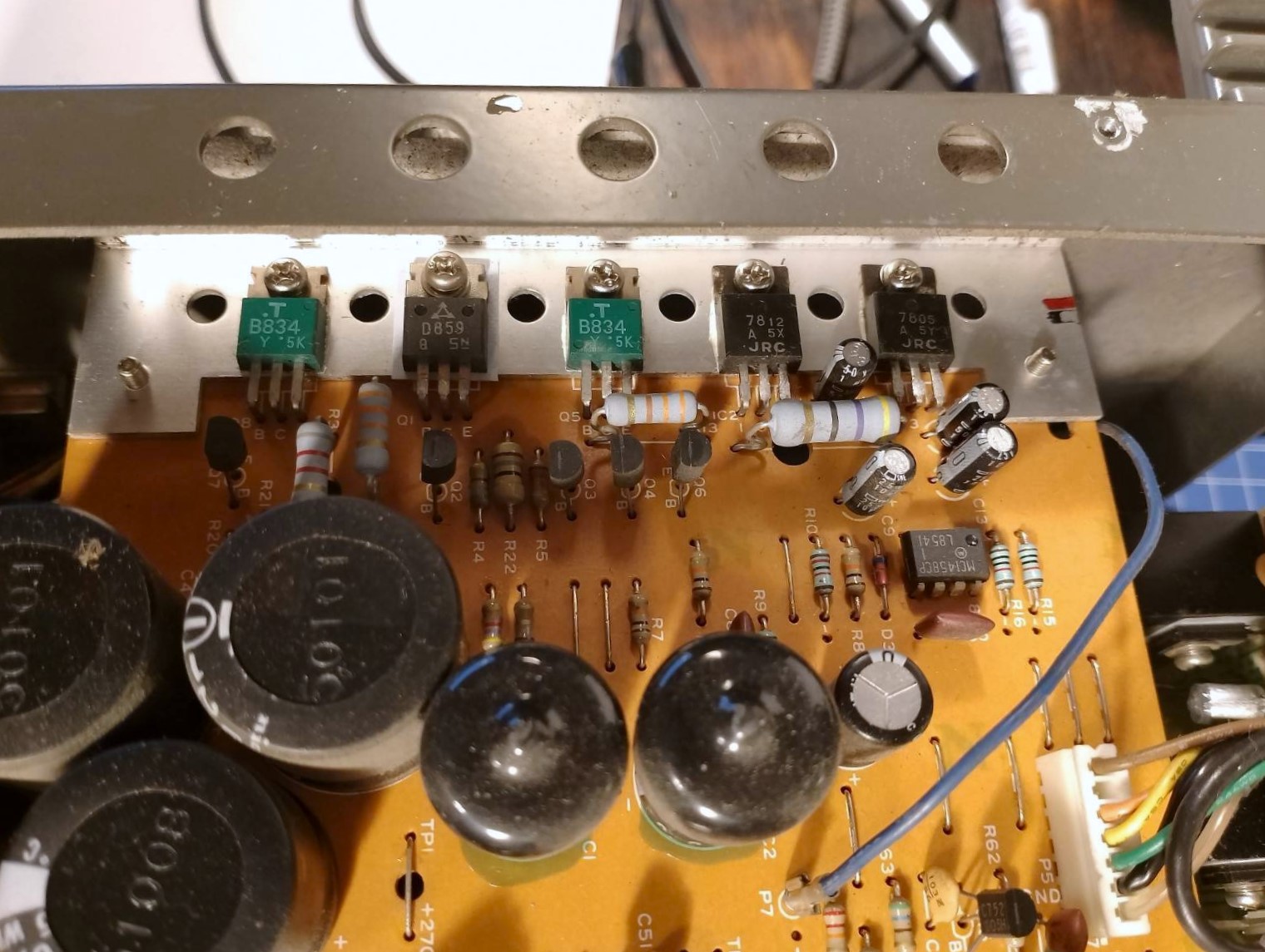
Aren’t those green transistor cases beautiful? I’ve seen similar ones in Polish audio equipment. CEMI plants sometimes released power transistors in TO220 packages in this color. Why am I mentioning this? I wonder if this proves that they were produced under a Japanese license like Polish electrolytic capacitors, or is it just a coincidence.
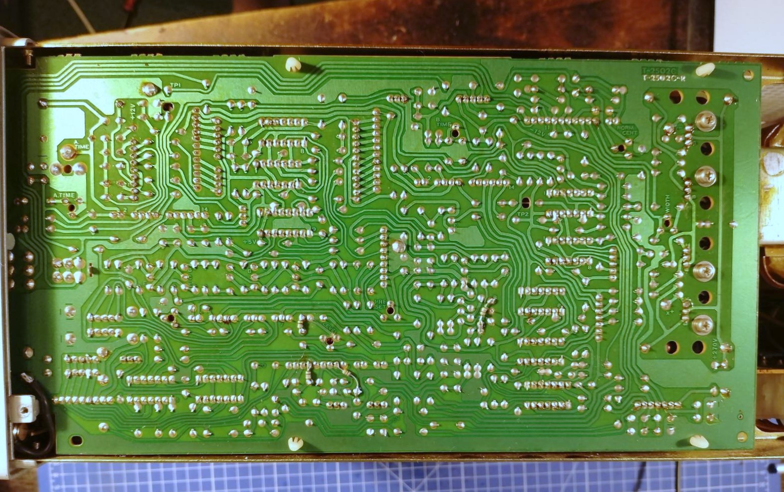
This is how the track plate Y looks like. For the purposes of the photo, I took off the shielding metal sheet.
And here we see the culprits of all the commotion. On the right side of the photo you can see the switches that needed cleaning.
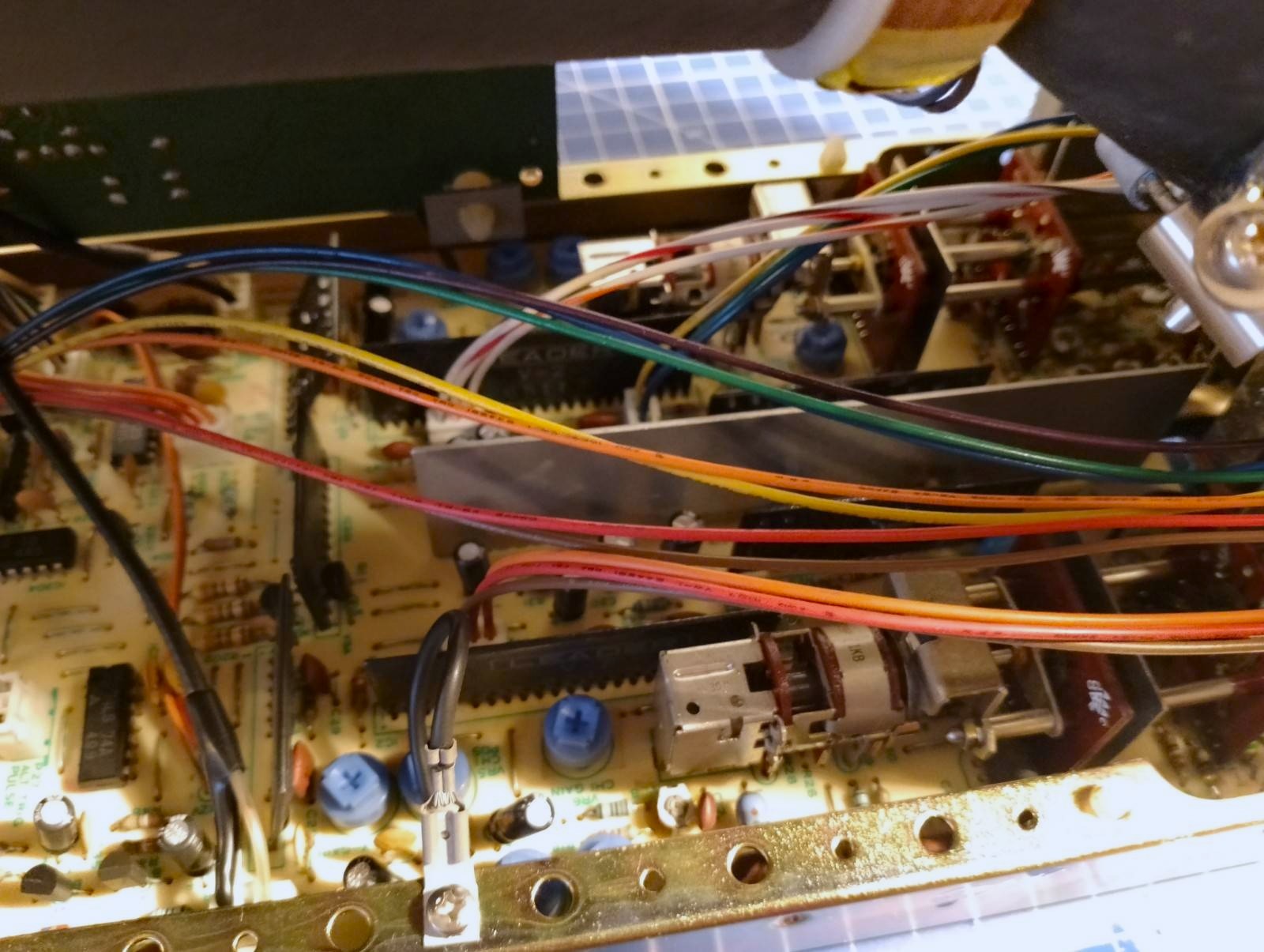
Photo from below.
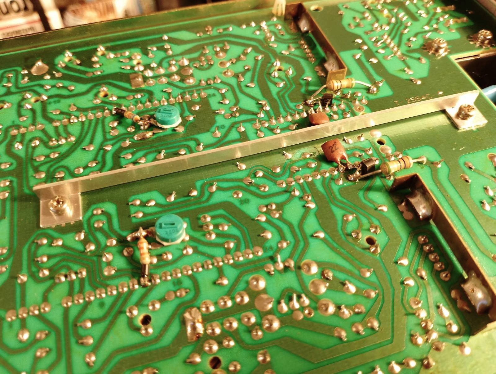
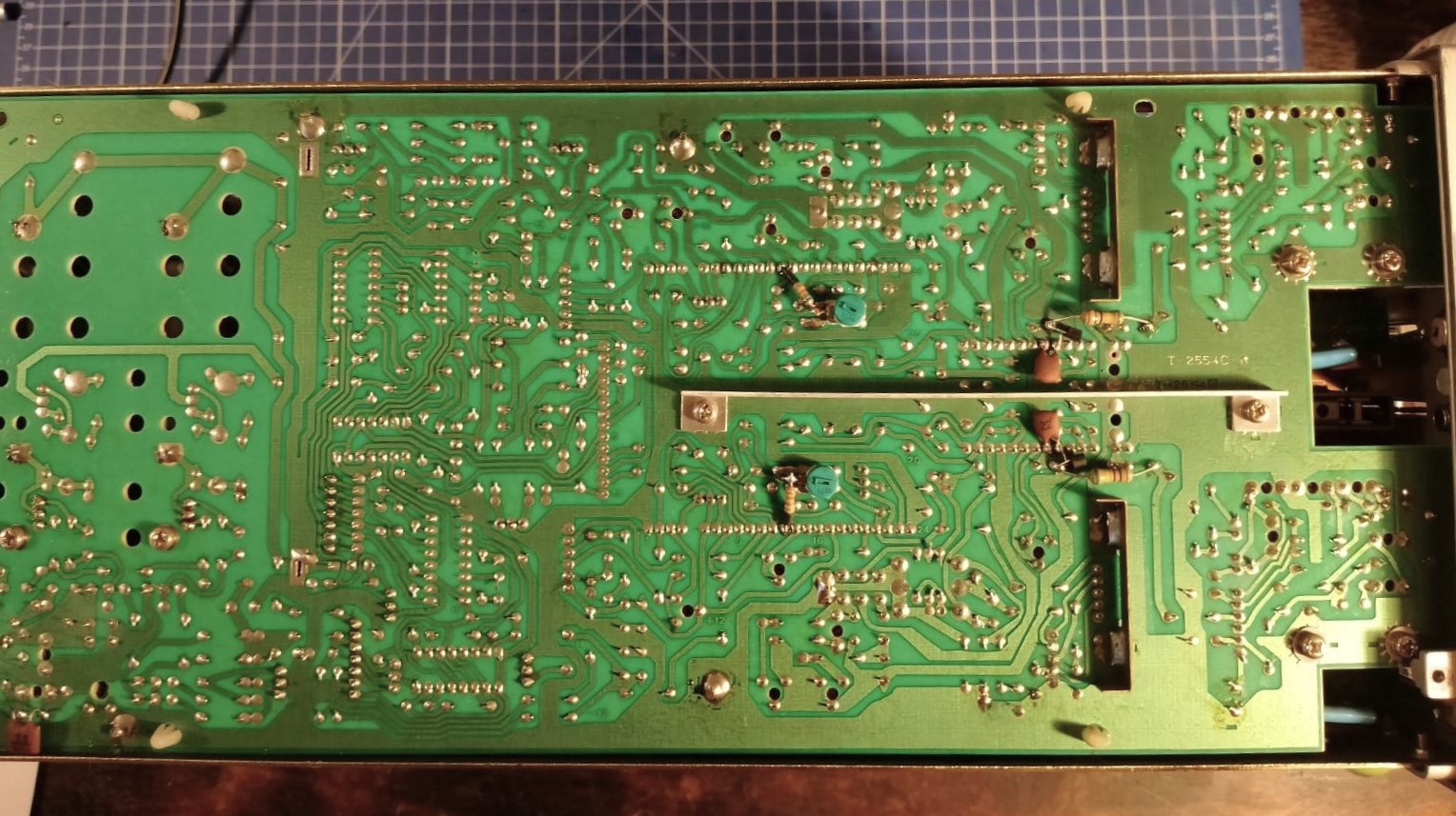 Visible elements soldered from the bottom of the PCB. I wonder if this improvement was implemented during production or maybe it was like this from the beginning?
Finally, we can look at the horizontal deflection plate with equally pesky switches.
Conclusion
After proper cleaning, the oscilloscope works like a charm. I’m glad I was able to put my gear on the altar of science. Or maybe you have some interesting measuring equipment? Write in the comments!